
Two UHF RFID tags can use similar chips and still perform very differently in the same application. A tag that reads reliably across a workbench may become difficult to detect when attached to a metal enclosure, positioned at an angle, or used with a different reader antenna.
This is because UHF RFID reading range is not determined by the chip alone. It depends on the interaction between the tag’s chip and antenna, the reader’s transmitted power and receiving capability, the reader antenna, tag orientation, the mounting surface, and the surrounding environment.
Understanding these factors helps engineers and technical buyers compare tags more accurately, identify performance limitations, and select a suitable design for the intended application.
This article focuses on passive UHF RFID tags, including RAIN RFID tags operating under the applicable regional UHF configuration.
1. How Does Passive UHF RFID Communication Work?
A passive UHF RFID system generally consists of three main elements:
- RFID reader: Generates and transmits an RF signal and receives the tag’s response.
- Reader antenna: Radiates the signal toward the tag and receives the returning signal.
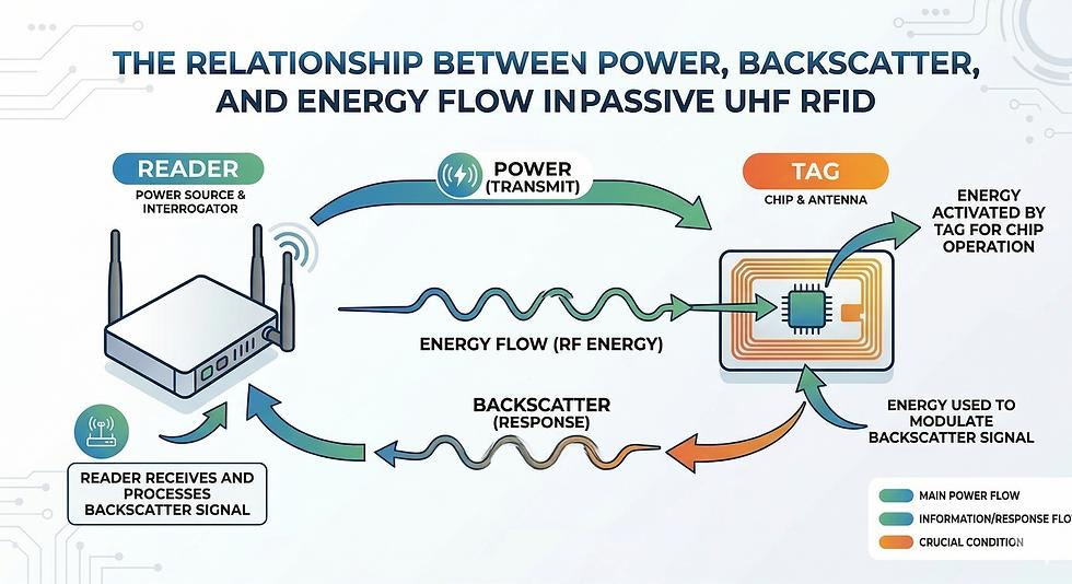
- RFID tag: Uses an antenna to collect energy from the reader’s signal and an integrated circuit (IC) to process commands and return data.
Unlike an active radio transmitter, a conventional passive UHF RFID tag does not use its own battery to transmit a continuous radio signal. It harvests energy from the reader’s RF field and responds through backscatter communication: the tag changes the reflection characteristics of its antenna so the reader can detect the encoded response.
This communication process creates two important requirements for successful reading:
- The RF energy arriving at the tag must be sufficient for the chip to operate.
- The tag’s response must return to the reader at a level the reader can detect and decode.
The practical reading distance is constrained by these requirements. Depending on the system, either the forward link—from reader to tag—or the reverse link—from tag back to reader—may be the limiting factor.
This is one reason why simply comparing chip sensitivity or reader transmit power does not provide a complete prediction of reading range.
2. How Does Chip Sensitivity Affect Reading Range?
Chip sensitivity describes how little RF power an RFID IC needs to operate under specified test conditions. It is commonly expressed in dBm.
For example, a chip with a sensitivity specification of −24 dBm requires less received power to reach that operating threshold than a chip specified at −20 dBm, assuming the figures are measured on a comparable basis. A more negative sensitivity value generally indicates a lower power requirement.
NXP publishes read-sensitivity specifications for several UCODE chips, including −24 dBm for UCODE 9 and −26.2 dBm for UCODE X. These are chip-level specifications, not guaranteed reading ranges for finished labels or tags. NXP+1
Why doesn’t a more sensitive chip automatically mean a longer read range?
Because the chip is only one component of the tag.
The chip must receive enough energy through the tag antenna and its matching network. If the antenna is poorly matched, inefficient, too small for the application, or detuned by the mounting surface, the complete tag may not perform as expected.
A chip’s specified sensitivity also does not describe the strength of the tag’s response as received by a particular reader. The reader must still detect and decode that response amid RF noise and interference.
| Factor | What it describes | Why it matters |
|---|---|---|
| Chip read sensitivity | Minimum RF power needed for chip operation under specified conditions | Influences the energy threshold for tag activation |
| Antenna efficiency | How effectively the antenna couples energy and radiates or scatters RF energy | Influences both energy collection and response performance |
| Antenna-to-chip matching | How well the antenna transfers RF power to the chip | Poor matching can reduce the power delivered to the IC |
| Reader receiver performance | Ability to detect and decode the returning response | A weak response may not be readable even when the tag activates |
Practical takeaway: Use chip sensitivity as one input when comparing designs. Do not treat it as a direct conversion to meters or as a substitute for finished-tag testing.
3. How Does Tag Antenna Design Influence Performance?
The antenna is a critical part of the tag’s RF system. Its dimensions, geometry, material, impedance, and interaction with the chip all affect how well the tag performs.
Antenna dimensions and geometry
Antenna dimensions must suit the intended operating frequency and physical form factor. In general, a larger available antenna area can provide more design flexibility, but size alone does not guarantee better performance.
A compact tag may be optimized for a small item or limited installation space. A larger design may allow a different balance of impedance, efficiency, bandwidth, and radiation behavior.
The appropriate design depends on the intended application, not simply on whether one antenna is larger than another.
Impedance matching
The antenna and chip have electrical impedances that must be matched appropriately for efficient power transfer. RFID tag antenna design therefore involves more than creating a shape that resonates at the desired frequency.
An antenna that performs well in one configuration may behave differently after the tag is attached to an object or enclosed in a different material.
Antenna efficiency and bandwidth
Antenna efficiency influences how effectively available RF energy is used. Bandwidth matters because UHF RFID systems operate across region-dependent frequency allocations rather than at one universal frequency worldwide.
A tag intended for one market or frequency configuration should not automatically be assumed to perform identically in another.
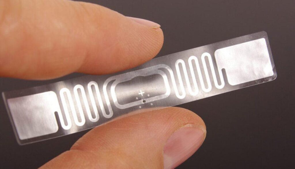
For product developers and label converters, this means that the chip, antenna layout, substrate, and final tag construction should be evaluated as one design. Replacing a chip or reducing the antenna footprint can affect the final RF behavior, even if the nominal frequency remains unchanged.
4. How Do Reader Power and Reader Antennas Affect Range?
The reader is the other major part of the link. Its settings and antenna characteristics can change the distance and area in which tags are reliably read.
Reader transmit power
Increasing reader transmit power can increase the RF energy reaching a tag and may help it activate at a greater distance. However, the benefit depends on the rest of the system.
Higher power does not automatically improve every read. The tag’s response must still be detected, and the system may encounter interference, unwanted reads, regulatory constraints, or application-specific limits.
The permitted operating power and frequency configuration depend on the applicable regional rules and equipment setup. Engineers should verify the legal limits for the intended deployment rather than using the maximum setting by default.
Reader antenna gain and directivity
Reader antennas differ in how they distribute RF energy.
- A directional antenna concentrates energy in a particular direction and may be appropriate for a defined read zone.
- A circularly polarized antenna can reduce sensitivity to tag rotation in some applications, although it does not eliminate orientation-related losses.
- A linearly polarized antenna can provide strong performance when the tag antenna’s polarization is aligned appropriately.
Antenna gain, beamwidth, placement, and orientation all affect where energy is concentrated and which tags can respond. GS1 identifies reader antenna directivity and gain as important factors in the shape of the readable volume. GS1 GO Customer Service Portal
Reader receiving capability
A reader must detect the tag’s backscattered response, not just transmit enough power to activate it. Receiver sensitivity, RF noise, interference, antenna performance, and the surrounding installation can all affect whether that response is decoded.
This distinction matters when diagnosing a system that appears to have sufficient reader power but still misses tags at certain positions.
Engineering takeaway: Reader power, reader antenna characteristics, and receiver performance should be considered together. A tag cannot be evaluated independently of the reader configuration with which it will be used.
5. How Do Polarization and Tag Orientation Affect Reading?
Polarization describes the orientation of the electric field in a radio wave. For many common UHF RFID designs, the tag antenna also has a preferred polarization.
When the reader antenna and tag antenna are poorly aligned, less energy may be coupled into the tag, and the returning signal may also be less favorably coupled to the reader antenna.
For example, a linearly polarized reader antenna may perform well when a compatible tag is aligned with it but experience a substantial reduction in performance when the tag is rotated.
The exact result depends on the antenna designs, tag construction, frequency, and environment.
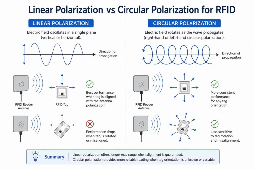
Linear versus circular polarization
| Reader antenna type | Potential advantage | Important consideration |
|---|---|---|
| Linear polarization | Can provide strong coupling when the tag is appropriately aligned | Performance may decrease when the tag rotates relative to the field |
| Circular polarization | Can accommodate a wider range of tag orientations in some applications | May not provide the same peak coupling as a well-aligned linear system |
| Multiple antennas or antenna orientations | Can improve coverage across different positions and directions | Requires suitable placement, configuration, and testing |
Circular polarization should not be treated as a universal solution. It can help reduce orientation sensitivity, but it does not eliminate losses caused by tag placement, shielding, detuning, or insufficient signal strength.
The important question is not simply, “How far can this tag read?” It is also, “At which orientations and positions can the system read this tag reliably?”
6. Why Do Mounting Surfaces and Surrounding Environments Matter?
A tag’s performance can change significantly after installation. The mounting surface and nearby materials may alter the antenna’s electrical behavior, absorb or reflect RF energy, or change the propagation path between the tag and reader.
Metal surfaces
Metal can change the current distribution and impedance of an antenna and alter its radiation behavior. A conventional UHF label designed for ordinary non-metallic surfaces may therefore perform poorly when directly attached to metal.
An anti-metal tag uses a design intended for metal mounting. Depending on its construction, it may incorporate a dedicated backing, spacing, ground-plane arrangement, or antenna structure suited to the application.
However, not every industrial tag needs an anti-metal design. The correct choice depends on the actual mounting surface and the intended use. For more detail, see the related article, Why Do RFID Tags Fail on Metal Surfaces?
Liquids and other nearby materials
Water and other materials can affect UHF RFID performance through absorption, detuning, and changes in the local electromagnetic environment. The magnitude of the effect depends on the material, its quantity, the tag position, and the system configuration. GS1 specifically identifies metal and water as materials that can influence RFID performance. GS1 GO Customer Service Portal
Installation geometry and nearby objects
Performance can also change when a tag is:
- Installed close to other objects or conductive structures.
- Placed inside an enclosure or behind a cover.
- Bent, curved, or mounted on an irregular surface.
- Positioned close to other RFID tags or RF-emitting equipment.
- Used in a location with strong reflections or other sources of interference.
A design that performs well in a free-space test may not behave identically when installed on the real product.
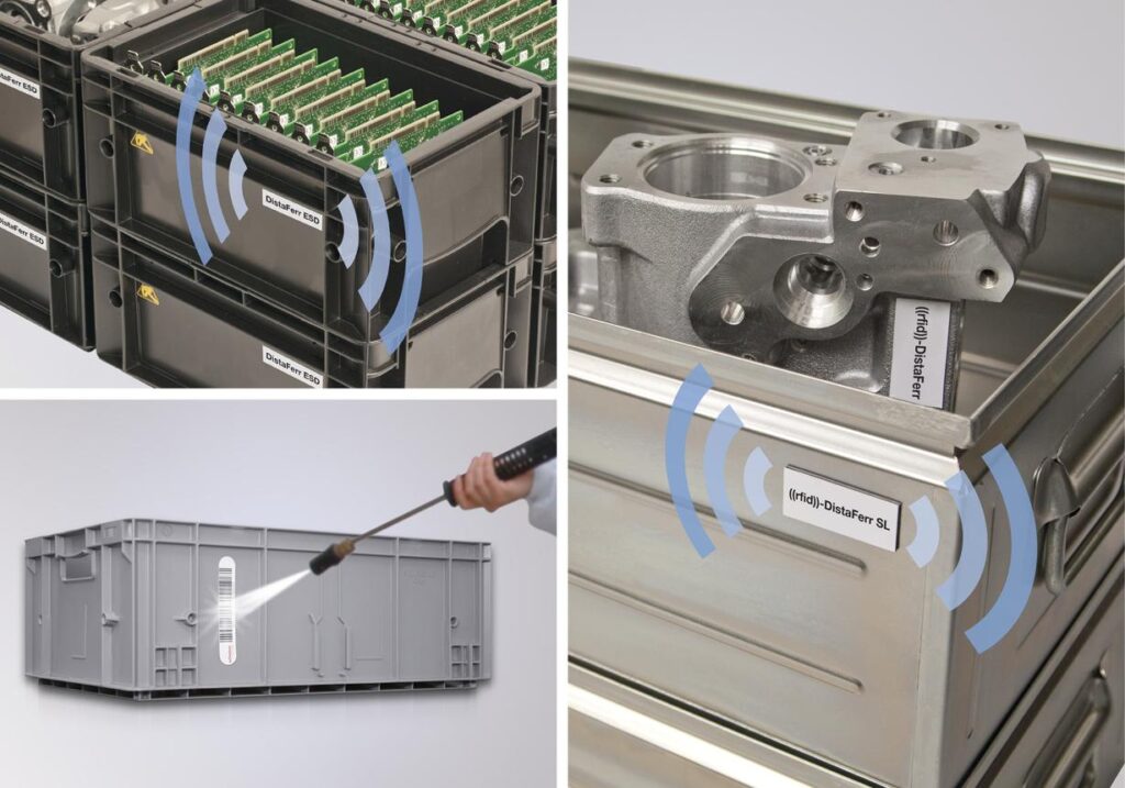
For this reason, tag evaluation should include the real mounting material, attachment method, available space, and nearby structures whenever possible.
7. How Should You Measure UHF RFID Reading Range Correctly?
A meaningful reading-range comparison requires a repeatable test setup. Comparing one tag tested at maximum reader power in an open room with another tested at a different power level, antenna angle, or mounting condition does not establish which tag is better.
Step 1: Define the intended application
Before testing, establish the required reading behavior.
Record:
- Application and target object.
- Required reading distance or read-zone dimensions.
- Mounting surface and installation method.
- Tag orientation and expected movement.
- Operating environment.
- Whether the system must read one tag or many tags in a defined period.
A fixed conveyor, handheld inventory task, portal, and cabinet may require very different performance characteristics.
Step 2: Standardize the equipment and settings
Record the reader model, reader antenna model, antenna gain, frequency configuration, reader power, and relevant reader settings.
Keep the test conditions consistent when comparing candidate tags. Where possible, use the same reader, antenna, cable arrangement, frequency configuration, and power setting.
Also record the test environment and any nearby objects that could affect the RF field.
Step 3: Control the tag position and orientation
Mount each tag using the intended attachment method and test it on the actual target material whenever possible.
Use defined distances and orientations rather than moving the tag by eye. If the application involves multiple orientations, include them as separate test conditions.
For tags mounted on metal, use the actual metal object or a representative sample with comparable geometry.
Step 4: Measure repeatable reading performance
At each test position, record whether the tag is read and repeat the measurement.
For more useful results, record both successful and missed reads across repeated attempts, rather than reporting only the farthest single successful read.
For example, an evaluation record might include:
| Test distance | Orientation | Attempts | Successful reads | Read success rate |
|---|---|---|---|---|
| 1 m | Position A | 100 | 100 | 100% |
| 2 m | Position A | 100 | 97 | 97% |
| 3 m | Position A | 100 | 82 | 82% |
| 4 m | Position A | 100 | 54 | 54% |
Illustrative test data only. These numbers are hypothetical and are not HIVE RFID product results or a recommended universal acceptance threshold.
This type of record helps distinguish a maximum observed read from a distance at which the system consistently meets the application’s requirements. The required success rate should be defined by the application, not assumed to be the same for every deployment.
Step 5: Repeat under realistic conditions
After the controlled comparison, test under representative operating conditions, including actual mounting, expected tag orientations, nearby materials, and normal reader placement.
Where multiple tags must be read, test the complete read zone and relevant tag population. A tag that can be read at a long distance in isolation may not deliver the required throughput or coverage in a populated environment.
Step 6: Document the results
A useful test report should include:
- Tag model, chip option, and dimensions, where known.
- Reader and reader antenna models.
- Frequency configuration and reader power.
- Antenna gain and polarization.
- Mounting surface and method.
- Distance and tag orientation.
- Number of attempts and successful reads.
- Environmental and interference conditions.
- Test date and any deviations from the standard setup.
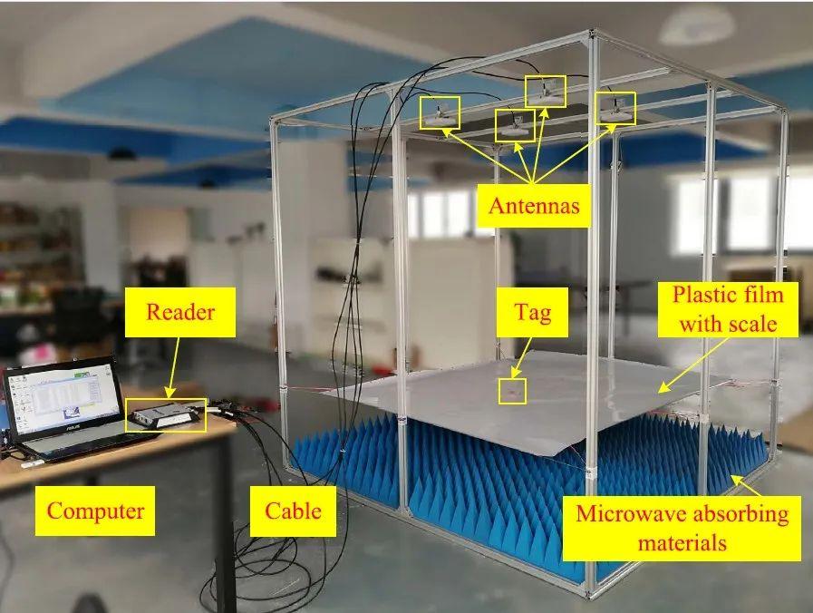
A good test result is not simply a number in meters. It is a documented performance result tied to a defined setup and application requirement.
8. Common Misconceptions About UHF RFID Reading Distance
| Misconception | What engineers should understand |
|---|---|
| A more sensitive chip always gives a longer read range | Chip sensitivity matters, but antenna efficiency, matching, reader performance, and installation also matter |
| More reader power always solves missed reads | Higher power may help tag activation, but it cannot eliminate every reverse-link, orientation, shielding, or interference problem |
| A tag’s advertised maximum distance is its usable range | Maximum distance may represent a particular test setup; reliable performance in the actual application must be verified |
| Tags with the same chip should perform similarly | Antenna design, materials, dimensions, and matching can produce different results |
| Circular polarization eliminates orientation problems | It may reduce sensitivity to orientation in some cases, but placement and propagation still matter |
| A free-space test predicts installed performance | Mounting surfaces, nearby objects, and environmental conditions can change the result |
| One reading-range number is enough to compare products | Reliable read rate, coverage, orientation tolerance, and application throughput may be more important |
GS1 likewise cautions against treating read range as a universal value and notes that the shape of the readable volume depends on the reader antenna and tag orientation. GS1 GO Customer Service Portal
9. How Can HIVERFID Support UHF Tag Evaluation?
HIVERFID supplies UHF RFID inlays, labels, and tags, with product selection and customization guided by the intended application.
For customers who need to evaluate reading performance, the most useful starting point is a clear description of the application and its constraints. Relevant information includes the required reading distance, target material, available tag dimensions, orientation, reader and antenna setup, and operating environment.
Where the application calls for a customized tag design, factors such as chip choice, antenna layout, physical dimensions, and mounting conditions can be considered together. Inlay design and manufacturing can support this engineering work without being treated as a separate primary sales proposition.
Actual performance should be confirmed against the specific tag configuration and intended installation. No chip option or tag design should be assigned a guaranteed reading distance without supporting test evidence.
What information should you provide for a technical evaluation?
- Application: What item or product needs to be identified?
- Required reading distance: What distance or read-zone dimensions are needed?
- Reader and antenna: Which models are used, if already selected?
- Mounting surface: Paper, plastic, glass, metal, liquid-adjacent, or another material?
- Tag size limitations: What are the maximum permitted length, width, and thickness?
- Tag orientation: How will the tag face the reader, and can it rotate?
- Operating environment: Indoor, outdoor, moisture, temperature variation, or nearby RF interference?
- Estimated quantity: What is the anticipated requirement?
Photos, drawings, and details of the existing test setup can make an initial assessment more useful.
10. Evaluate the System, Not Just the Tag
UHF RFID reading range results from several interacting factors. Chip sensitivity affects the energy required for operation, while antenna design and matching determine how effectively the tag couples to the RF field. Reader power, reader antenna characteristics, receiver performance, polarization, mounting materials, and environmental conditions further influence the result.
For engineers and technical buyers, the most reliable approach is to compare candidate tags under controlled conditions and then validate them in the intended application.
Rather than choosing a tag based solely on a maximum-distance claim, define the required read zone, standardize the test setup, record repeatable read rates, and confirm performance on the actual target object.
Need help evaluating a UHF RFID tag for your application? Share your required reading distance, reader and antenna details, mounting surface, available tag size, orientation, and operating environment. HIVE RFID can use these requirements as the starting point for discussing suitable UHF tag options and potential customization.


